
#pwm
1 post1 participant0 posts today


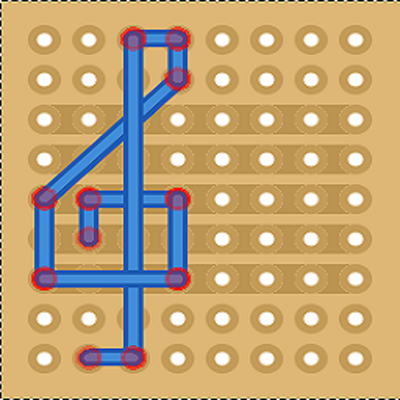
Simple PWM Filter PCB Build Guide
Here are the build notes for my Simple PWM Filter PCB Design. Below you can see it connected to my Pico Touch Board.
Warning! I strongly recommend using old or second hand equipment for your experiments. I am not responsible for any damage to expensive instruments!
If you are new to electronics and microcontrollers, see the Getting Started pages.
Bill of Materials
- PWM Audio Filter PCB (GitHub link below)
- 2x Suitable filter components, for example, per channel:
- 3x 1KΩ resistors
- 2x 100nF ceramic capacitor
- 1x 2u2 electrolytic capacitor
- Optional: Pin headers
- Optional: 2x 3.5mm TRS sockets (pcb mounted, see photos for footprint)
Build Steps
Taking a typical “low to high” soldering approach, this is the suggested order of assembly:
- All resistors.
- TRS sockets (if used).
- Disc capacitors.
- 3-way jumper headers (if used).
- Electrolytic capacitors.
Here are some build photos.
If the electrolytic capacitors will be bent over, then they should be bent and soldered in place before the header pins.
Testing
I recommend performing the general tests described here: PCBs.
PCB Errata
There are no known issues with this PCB at present.
Enhancements:
- As previously mentioned it might have been useful to label the left and right channels and use the alternative resistor circuit symbol.
- It might have been useful to include solder jumpers to allow the simple combining of the left and right inputs and outputs
- Some additional connection points for an oscilloscope might have been useful too.
Sample Applications
Here are some applications to get started with:
- Pico Touch Board Audio – 3x 1K resistors, 3x 100nF capacitors, and 1x 2u2 electrolytic per channel.
Experimenter board
Rather than fixed components, it is possible to solder on round pin header sockets to allow components to be pushed into place. This means that it is fairly easy to experiment with alternative component values to see what difference they make.
When doing this, I only soldered up one channel, but joined the left/right inputs and outputs by adding a solder bridge across the pin headers. I also soldered additional pins to the spare GND connections from the second channel. This allows plenty of pin connections for an oscilloscope.
The connections for components aren’t as tight as they could be, especially for low-wattage components with pretty thin legs.
It might be that just continuing to use solderless breadboard for experiments is simpler, but it was pretty useful to be able to leave oscilloscope connections and the input and output connected whilst experimenting.
Board Manufacturing
These boards are sized to allow them to be ordered in a 2×4 panel if required, and still remain within a 100x100mm footprint. I used jlcpcb’s panel options with v-cuts and it was really quite inexpensive to do.
Closing Thoughts
I’m still not sure I really understand enough analog electronics to get the theory of how a dual-stage filter incorporating a potential divider still works, and any simulation is still not quite matching my theory to experiment.
As has been said, “in theory, theory and practice are the same, in practice they are different”.
This might make some proper practicing a bit easier.
Kevin
Simple PWM Filter PCB Design
Having spent a bit of time attempting (although I’m not sure I’m succeeding yet) to understand how to get a useful filter for my Pico Touch Board Audio, I thought it would be useful to have a simple template PCB that could be used for a range of PWM low-pass filtering options.
This is my design.
Warning! I strongly recommend using old or second hand equipment for your experiments. I am not responsible for any damage to expensive instruments!
If you are new to electronics and microcontrollers, see the Getting Started pages.
The Circuit
This is following on from the discussion in Pico Touch Board Audio creating the template for a simple two-stage low-pass filter with an option for including a potential divider resistor to drop the overall voltage too.
I’ve doubled the circuit to allow for stereo in and out if required and have included both 3.5mm TRS sockets and pin jumper headers for both input and output.
It requires no power, being a completely passive filter.
If stereo is not required, then just one of the circuits can be populated – ideally the one connected to the TRS tip.
PCB Design
There isn’t much to this pcb layout really. I was particularly keen to keep the PCB away from specific values of components, so instead used the silkscreen to present a pseudo-circuit diagram to make it clear which components are which.
I’ve also tried to leave enough room for the electrolytic capacitors to allow them to be bent over if required.
Closing Thoughts
With hindsight, I can think of a couple of additions that would have been useful on the silkscreen – labelling which circuit is left and right for example.
And having the boards back, I should have added manual “wavy line” resistor diagrams rather than rectangles, but it is enough for what I need.
And it might have been useful to include some additional test points for connecting an oscilloscope.
Kevin

Converting a Sprinkler System to DC - Famously, Nikola Tesla won the War of the Currents in the early days of electrific... - https://hackaday.com/2025/08/22/converting-a-sprinkler-system-to-dc/ #greenhacks #conversion #sprinkler #solenoid #drv103 #grass #lawn #pwm #ac #dc
Hackaday · Converting A Sprinkler System To DCFamously, Nikola Tesla won the War of the Currents in the early days of electrification because his AC system could use transformers to minimize losses for long distance circuits. That was well bef…
FPV Protocols Explained (CRSF, SBUS, DSHOT, ACCST, PPM, PWM and more)
This post will give a broad overview of all the common RC protocols in FPV, and how they fit into the communication system in an FPV drone, and what their differences are.

Oscar Liang · FPV Protocols Explained (CRSF, SBUS, DSHOT, ACCST, PPM, PWM and more) - Oscar LiangI will explain the common RC protocols between flight controller, radio receiver and transmitter communications, including SBUS, CRSF, PWM, DSMX, FPort etc.
I just found this blog post about how to make #music using #pwm on #lego #powerfunctions #motors. not that I want to, but there is quite some technical information in there.
Gets me thinking about building a simple #train motor Forth library. To run on a microcontroller inside your #locomotive to which you connect via wifi ... hmmm ... @f4grx what do you think?!
https://brickexperimentchannel.wordpress.com/2023/05/06/music-with-lego-motors-pwm/
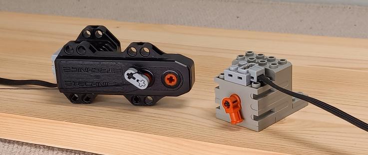
Brick Experiment Channel · Music with Lego motors (PWM)How to create music with PWM signals and Lego motors. You can generate melodies like The Imperial March tune, demonstrated in the following video. The principle The sound is produced by driving Leg…
A Repeater for WWVB - For those living in the continental US who, for whatever reason, don’t have access... - https://hackaday.com/2025/08/07/a-repeater-for-wwvb/ #clockhacks #wristwatch #amplifier #arduino #clock #radio #watch #wwvb #pwm
Hackaday · A Repeater For WWVBFor those living in the continental US who, for whatever reason, don’t have access to an NTP server or a GPS device, the next best way to make sure the correct time is known is with the WWVB …
Pico Touch Board Audio
I wanted to go back to my Pico Touch Board PCB Design and see if there was a way to make it more stand-alone. The original design was to make it a MIDI controller, but that isn’t the only option.
https://makertube.net/w/tADSyrPrUdR1mx7yKRXZTC
Warning! I strongly recommend using old or second hand equipment for your experiments. I am not responsible for any damage to expensive instruments!
These are the key Arduino tutorials for the main concepts used in this project:
If you are new to microcontrollers, see the Getting Started pages.
Parts list
- Pico Touch Board PCB – built
- Resistors: 1x 220Ω, 1x 1K
- Capacitor: 1x 100nF ceramic, 1x 22uF electrolytic
- Breadboard and jumper wires
The Circuit
Most of the GPIO are linked out to the touch pads, but the three analog inputs are still available. They are added on to the header on the right hand side of the board at the top, so we can use one of these as an audio output.
Initially, I thought of connecting it to an 8Ω speaker. If I was using an Arduino then I’d use a 220Ω resistor in series to limit the current to less than 20mA. But as I’m using a Pico, the maximum current has to be a lot less. I seem to recall it is a little complicated, and there are some options, but I have a figure of around 4mA that I tend to work to. It is also running at 3.3V, which means that it would need an in series resistor of 3.3 / 0.004 = 825Ω. This would work, but the speaker will be really quiet!
So I ditched that idea (there is a software reason too, but I’ll talk about that in a moment) and went straight to a PWM output with a low-pass filter to try to give me some vaguely useful as a line-out signal.
I’ve not done the calculations, but instead went a bit “hand-wavy”, combing a 1K and 220Ω resistor to drop the voltage, along with a 100nF capacitor. I’ve also added a 22uF capacitor to remove the DC bias.
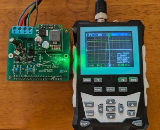
That seems to give me something useful, but as you can see from the trace below of a square wave PWM output, there is a lot of room for improvement!
Update
Ok, so going back and doing this semi-properly as per my notes from Arduino PWM Output Filter Circuit, I can see that the 1K and 220Ω resistors can be treated as a 180Ω equivalent (take them as two in parallel) for the filter circuit, which means a cut-off of around 8kHz which ought to be pretty good….
But reducing a 3V3 signal to around 20% leaves for quite a low level of audio – around 660mV peak to peak. It would probably be better to aim for a reduction of around a half.
Using a 1K and 500Ω resistor would be an equivalent resistance of 333Ω, so putting that into a low pass filter calculator gives a cut-off frequency of around 5kHz for a 100nF capacitor.
Weirdly the only thing that really seems to improve things is to raise that capacitor value to 1uF. My calculation would suggest a cut-off frequency of around 480Hz which is pretty small for an audio signal. But it seems to work.
The PWM frequency I was seeing was coming in at around 120kHz so should be plenty high enough to get filtered out. In the Circuitpython code, it is apparently chosen to support the number of bits required at the base clock frequency whilst being inaudible. For the RP2040 running at 125MHz, and with the chosen 10 bit resolution (more here) this is:
- 125,000,000 / 1024 = 122,070 Hz
A 5kHz (or even 8kHz) cut-off I thought ought to be fine, but Davide Bucci on Mastodon explained for me:
“120kHz is 25 times 4.7kHz, that is about 1.4 decades and with a first-order filter you have a tad less than 30dB of attenuation, that is not a lot. A signal at 3.3V peak to peak at 120kHz becomes about 100 mV on the output after the filter.”
So switching to 1uF, as Davide explains: “if you put 1µF, you are indeed filtering a decade lower, therefore you gain 20dB in the attenuation and the 100mV become 10mV, much less noticeable.”
The alternative is to repeat the 1K+100nF stage and add a second order filter which also seems to work pretty well.
The final circuit that works fine for me at present, will be on of the following.
The first is less components but assumes that the frequencies won’t go much about ~1KHz or so. That is ok for my current setup but would limit the audio range a fair bit.
This is the output of the two-stage filter. It is so much better!
The Code
I wanted to stick with Circuitpython, so my initial thought was to use simpleio.tone() to generate a tone based on a frequency from an IO pin. However, this has the problem that the code is blocking whilst the tone is playing which isn’t very useful.
Instead I went straight to synthio. It turns out that using synthio was actually a lot easier than the “simple” simpleio…
Here is the basic code to generate an ASR-shaped square wave on a PWM audio output on GPIO 28 based on the touch pads as input.
import board
import touchio
import synthio
import audiopwmio
from adafruit_debouncer import Debouncer, Button

audio = audiopwmio.PWMAudioOut(board.GP28)
synth = synthio.Synthesizer(sample_rate=22050)
audio.play(synth)
synth.envelope = synthio.Envelope(attack_time=0.1, release_time=0.6, sustain_level=1.0)

touchpins = [
    board.GP2, board.GP3, board.GP4, board.GP5,
    board.GP6, board.GP7, board.GP8, board.GP9,
    board.GP10, board.GP11, board.GP12, board.GP13,
    board.GP14, board.GP15, board.GP16, board.GP17,
    board.GP18, board.GP19, board.GP20, board.GP21, board.GP22
]

THRESHOLD = 1000
touchpads = []
for pin in touchpins:
    t = touchio.TouchIn(pin)
    t.threshold = t.raw_value + THRESHOLD
    touchpads.append(Button(t, value_when_pressed=True))

while True:
    for i in range (len(touchpads)):
        t = touchpads[i]
        t.update()

        if t.rose:
            synth.press(60+i)

        if t.fell:
            synth.release(60+i)
I did experiment with overclocking the Pico to give double the PWM frequency, using
microcontroller.cpu.frequency = 250_000_000
But although this did double the PWM frequency to around 244kHz, it didn’t seem to make much difference for the filtered signal.
Battery Power
One last thing I wanted to explore was if it was possible to power the touchboard with batteries. I left in a number of power options, so for this one I’m using the 5V/GND pin header. I’ve included a couple of capacitors for smoothing, and need to add the 1N5817 diode as shown below.
This requires the following additional components:
- 1x 1N5817 Schottky diode.
- 1x 100nF ceramic capacitor.
- 1x 47uF electrolytic capacitor.
- Jumper wires.
- 3 or 4 battery box.
The 5V/GND header pins connect to the Raspberry Pi Pico’s VSYS pin via the Schottky diode. The 1N5817 has a typical voltage drop of 0.45V, so combined with the Raspberry Pi’s accepted input voltage of 1.8V to 5.5V this means that ideally two or three AA batteries (at 1.5V each) would work. Four 1.2V rechargeables might be an option too.
It might be possible to get away with four 1.5V AAs, but that would give an input voltage of just over 5.5V, so I think that is probably pushing things too far. It might be a good use for some spent AAs though that are no longer reading a full 1.5V…
One of the downsides of battery power is that the touch works best when your fingers are at the same GND potential as the board. It works best if the GND pin of the (unpopulated) barrel jack is touched when using the board.
Closing Thoughts
With hindsight it would have been useful to have included a simple PWM output stage on the original board, but it is relatively straight forward to add one.
It might even be worth me making an add-on board that will connect to the header pins of the power and analog pins containing the simple passive filter components.
What is pretty impressive though, is how easy it is to use synthio with Circuitpython.
Kevin

 Hacker News
 Show HN: My GPU Fan Saga – A DIY ATX Fan Controller
https://shafq.at/my-gpu-fan-saga.html
#ycombinator #firmware #hardware #tech #pwm #attiny85 #fan
Ayan Shafqat · My GPU Fan SagaHaving a problem-solving mindset is incredibly valuable and rewarding, especially when it leads to exciting DIY adventures. My latest experience with a noisy GPU fan turned into just such an opportunity. It guided me through fascinating explorations involving ATX power, MOSFET motor drivers, Pulse Width Modulation (PWM), ATTiny85's bit-banged 1-wire …
ESP32 S3 DevKit Experimenter PCB Build Guide
Here are the build notes for my ESP32 S3 DevKit Experimenter PCB Design.
Warning! I strongly recommend using old or second hand equipment for your experiments. I am not responsible for any damage to expensive instruments!
If you are new to electronics and microcontrollers, see the Getting Started pages.
Bill of Materials
- ESP32S3 DevKit Experimenter PCB (GitHub link below)
- ESP32S2 DevKitC (official or clone – see ESP32 S3 DevKit)
- MIDI Circuit:
- 1x H11L1 optoisolator
- 1x 1N4148 or 1N914 signal diode
- Resistors: 1x 10Ω, 1x 33Ω, 1x 220Ω, 1×470Ω
- 1x 100nF capacitor
- Either: 2x MIDI DIN sockets (see photos and PCB for footprint)
- Or: 2x 3.5mm stereo TRS sockets (see photos and PCB for footprint)
- Pin headers and jumpers
- Optional: 6-way DIP socket
- Audio Output Circuit:
- Resistors: 2x 1K, 2x 2K
- 2x 10uF non-polar capacitors
- 2x 33nF ceramic capacitors
- 1x 3.5mm stereo TRS socket
- Power Circuit:
- 1x 7805 regulator
- Electrolytic Capacitors: 1x 100uF, 1x 10uF
- 1x 100nF Ceramic Capacitor
- SPST switch with 2.54mm pitch connectors
- 2-way header pins
- 2.1mm barrel jack socket (see photos and PCB for footprint)
- 8x 10K potentiometers (see photos and PCB for footprint)
- Optional: 2x 22-way pin header sockets
- Additional pin headers or sockets as required
Each circuit module is effectively optional. The position of the 22-way headers will depend on which type of module is used. The clone versions are 1 pin row wider than the official version.
There are some solder-bridge configuration options too, which will be discussed later.
Build Steps
Taking a typical “low to high” soldering approach, this is the suggested order of assembly:
- All resistors and diode.
- DIP socket (if used) and TRS socket(s).
- Disc capacitors.
- Switch
- Jumper and pin headers.
- 22-way pin sockets (if used).
- Non-polar and electrolytic capacitors.
- 7805 regulator.
- Potentiometers.
- DIN sockets.
Here are some build photos for the MIDI DIN version of the board. If using MIDI TRS sockets, then these can be installed at the same time as the audio socket.
If using 22-way headers for the DevKit, then the position will depend on which type of DevKit module is being used. In the photo below, I’ve installed 3 sets of 22-way headers to allow me to use either a clone or official module.
The remaining components can almost be installed in any order that makes sense at the time.
Once the main build is complete, two additional capacitors are required for the audio PWM output circuit. Two 33nF capacitors should be soldered across the 1K resistors. This is probably best done on the underside of the PCB as shown below.
Ignore the red patch wire. I managed to cut through a track whilst clipping the excess leads after soldering.
Configuration Options
The following are configurable and can be set by using pin headers and jumpers; solder bridges; or possibly wire links.
- UART for MIDI – pin header + jumpers.
- Audio Output – can be disconnected by breaking solder jumpers on rear of the board under 1K/2K resistors.
- GPIO used for RV3 and RV8 – can be set using solder jumpers on rear of the board under RV3 and RV8.
Testing
I recommend performing the general tests described here: PCBs.
WARNING: The DevKit can be powered from either the USB sockets or the new power circuit, but not both at the same time.
The sample application section includes some simple sketches that can be used to test the functionality of the board.
PCB Errata
There are the following issues with this PCB:
- I should have oriented the DevKit the other way up so that the USB sockets were on the edge of the board, not overhanging the prototyping area!
- The Audio filter requires additional capacitors (see notes).
Enhancements:
- None
Sample Applications
Analog Potentiometers
The following will read all 8 pots and echo the values to the serial monitor.
void setup() {
  Serial.begin(115200);
}
void loop() {
  for (int i=0; i<8; i++) {
    int aval = analogRead(A0+i);
    Serial.print(aval);
    Serial.print("\t");
  }
  Serial.print("\n");
  delay(100);
}
Audio PWM Output
The following will output a 440 Hz sine wave on the PWM channel on GPIO 15. Change to 16 to see the other one.
int pwm_pin = 15;#define NUM_SAMPLES 256uint8_t sinedata[NUM_SAMPLES];#define PWM_RESOLUTION 8#define PWM_FREQUENCY 48000#define TIMER_FREQ 10000000#define TIMER_RATE 305#define FREQ2INC(f) (f*2)uint16_t acc, inc;void ARDUINO_ISR_ATTR timerIsr (void) { acc += inc; ledcWrite (pwm_pin, sinedata[acc >> 8]);}hw_timer_t *timer = NULL;void setup () { ledcSetClockSource(LEDC_AUTO_CLK); for (int i=0; i<NUM_SAMPLES; i++) { sinedata[i] = 127 + (uint8_t) (127.0 * sin (((float)i * 2.0 * 3.14159) / (float)NUM_SAMPLES)); } timer = timerBegin(TIMER_FREQ); timerAttachInterrupt(timer, &timerIsr); timerAlarm(timer, TIMER_RATE, true, 0); ledcAttach(pwm_pin, PWM_FREQUENCY, PWM_RESOLUTION); inc = FREQ2INC(440);}void loop () { }I’m getting a pretty good signal with a 33nF filter capacitor, but the signal still retails some bias. I’m getting a Vpp of around 1.1V.
But it starts out with a swing from around -200mV to +900mV. But this slowly improves over time and after a few minutes is much closer to a nominal -500mV to +600mV. I guess that is probably my cheap capacitors!
MIDI
Most of the MIDI monitors, routers and sending projects I have should work with the MIDI setup. In the default configuration, using UART0 (GPIO 43/44) for MIDI, that appears as Serial0 or the default MIDI configuration (more on serial ports on the ESP32S3 here: ESP32 S3 DevKit).
So the Simple MIDI Serial Monitor should just work and anything sent to the board should:
- Illuminate the on-board (RGB) LED.
- Echo back out to the MIDI OUT port.
Here is the full test code:
#include <MIDI.h>

MIDI_CREATE_DEFAULT_INSTANCE();

void setup() {
  MIDI.begin(MIDI_CHANNEL_OMNI);
  pinMode (LED_BUILTIN, OUTPUT);
}

void loop() {
  if (MIDI.read()) {
    if (MIDI.getType() == midi::NoteOn) {
        digitalWrite (LED_BUILTIN, HIGH);
        delay (100);
        digitalWrite (LED_BUILTIN, LOW);
    }
  }
}
Note: as the MIDI is (probably) hanging of UART0 which is also routed to the USB “COM” port, it will be easier to upload via the USB “USB” port. This won’t clash with the MIDI circuitry on UART0.
Closing Thoughts
I seem to be having a run of “doh” moments with a few of these PCBs, but then that is the price I pay for taking shortcuts by only designing them in my head rather than prototyping them first!
But arguably, it is still a lot easier using a soldered PCB than attempting to build the various elements on solderless breadboard, so in a way that is what these prototypes are largely for.
So apart from the filter issue which is actually fairly easily solved, this seems to work pretty well.
Kevin
ESP32 S3 DevKit Experimenter PCB Design
This a version of the ESP32 WROOM Mozzi Experimenter PCB for the latest ESP32-S3 DevKitC board I’ve found.
For the background on the boards themselves, see my notes here: ESP32 S3 DevKit.
Warning! I strongly recommend using old or second hand equipment for your experiments. I am not responsible for any damage to expensive instruments!
If you are new to Microcontrollers, see the Getting Started pages.
The Circuit
This is mostly just breaking out the pins of the ESP32S3 DevKitC to header pins, but there are a couple of additional features too:
- There are additional rows of headers. The idea is to support the official and clone boards, which means coping with the fact the clone boards are 1 row of pins wider than the official boards.
- There is MIDI IN and OUT with jumpers to select UART0 or UART1.
- There is a stereo PWM output circuit (see notes below).
- There are 8 potentiometers connected to ADC1.
- There is a 7805 or equivalent regulator to provide power if required.
One slight complication is the possibility that GPIO3 (ADC1_CH2) is required as a STRAPPING pin or that GPIO8 (ADC1_CH7) is required for I2C (more in the previous post) so there is a solder bridge option for either of them to switch over to GPIO10 (ADC1_CH9) instead.
The complete GPIO usage is as follows:
GPIO0On board BOOT buttonGPIO 1-8Potentiometer 1-8GPIO 10Optional replacement for GPIO 3 or 8GPIO 15, 16PWM audio outputGPIO 43, 44MIDI if UART0 is selectedGPIO 17, 18MIDI if UART1 is selectedGPIO 1-20Analog breakout area*GPIO 21, 38-49Digital breakout area*GPIO 38 or 48Onboard RGB LED* As already mentioned some of these have alternative or preferred functions.
Audio PWM Output
I based this on the output circuit for my ESP32 WROOM Mozzi Experimenter PCB Design, but I was forgetting that the original ESP32 has a DAC and so only requires a potential divider to reduce the voltage levels and a capacitor to remove the DC bias.
The ESP32S3 does not have a DAC, so the output will have to be via PWM if no external DAC is added. This means this output circuit really needs a low-pass filter to smooth out the pulses from the PWM signal.
That hasn’t been included in the design, but can be implemented by adding capacitors across the terminals of the 1K resistors, as shown below.
Following the discussion from Arduino PWM Output Filter Circuit, we can see that a 2K/1K potential divider can (loosely) be treated as a ~666K resistor for the purposes of a low-pass filter calculation. So this gives me various options in terms of capacitor size as follows.
ResistorCapacitorRoll-off frequency666K10nF24 kHz666K33nF7 kHz666K68nF3.5 kHz666K100nF2.4 kHzThe greatest smoothing will come with the lowest cut-off, but 2.4kHz or 3.5kHz will limit the higher audio frequencies somewhat. But a 10nF might not give me enough smoothing.
It will also depend somewhat on the PWM frequency chosen. The higher, i.e. above the audio frequency range required, the better.
I’ll start with adding 33nF and see how that looks then might change with some experimentation.
If an external DAC is used, then there are solder jumpers provided that can be broken to disconnect this part of the circuit anyway.
PCB Design
I initially considered only breaking out GPIO pins that weren’t being used for additional functions, but then decided I’d just break them all out alongside the prototyping area. Any pins that might be problematic or have an existing function on the board are labelled in brackets – e.g. (GPIO 43).
The solder jumpers for the GPIO/ADC choices are on the underside of the board.
As previously mentioned, the headers are arranged such that it will support the official DevKitC or the slightly wider clones.
The jumper for UART selection for MIDI can serve as a “disable MIDI to allow use of the serial port” function too if required.
There is also a twin jumper option for direct 5V input instead of going via the barrel jack and regulator.
Closing Thoughts
The omission of the capacitors in the PWM filter is a small annoyance, but it is relatively easily fixed.
Apart from that, there is a fair bit included on this board. It should serve as a good platform for further experimentation.
Kevin

Want to learn about Pulse Width Modulation (PWM) on hardware, but don't have any actual hardware?
We've got you covered with our newest addition to the TinyGo Tour with simulated hardware using WebAssembly in your browser!
https://tinygo.org/tour/pwm/
#tinygo #golang #embedded #pwm #wasm #webassembly
TinyGoPWMUsing the PWM peripheral of common microcontrollers.
Arduino Pro Mini MIDI USB CV PCB Build Guide
Here are the build notes for my Arduino Pro Mini MIDI USB CV PCB Design.
Warning! I strongly recommend using old or second hand equipment for your experiments. I am not responsible for any damage to expensive instruments!
If you are new to electronics and microcontrollers, see the Getting Started pages.
Bill of Materials
- Arduino Pro Mini USB MIDI Host CV PCB (GitHub link below)
- Arduino Pro Mini (3V3/8MHz version)
- Mini USB Host Shield 2.0
- 1x H11L1
- 1x MCP6232
- Diodes: 1x 1N4148 or 1N914 signal diode; 2x BAT43 Schottky
- Resistors: 10Ω, 33Ω, 1x 220Ω, 330Ω, 470Ω, 3x 1K, 2K7, 5K6, 2x 10K (*)
- Ceramic Capacitors: 4x 100nF (*)
- 1x 3.5mm stereo TRS
- Either 2x 3.5mm stereo TRS OR 2x 5-pin, 180 degree MIDI DIN sockets
- Pin headers
- Optional: 2x 12-way pin header sockets
- Optional: 1x 6-way DIP socket; 1x 8-way DIP socket
* The PCB shows the use of 2x 10nF and 2x 200Ω resistors for the PWM filter part, but 100nF and 1K work much better.
Optional: Power circuit
- 7805 regulator
- Electrolytic Capacitors: 1x 10uF, 1x100uF
- Ceramic Capacitors: 1x 100nF
- 1x SPST power switch 2.54mm pitch
Build Steps
Taking a typical “low to high” soldering approach, this is the suggested order of assembly:
- Diodes
- Resistors
- DIP sockets (if used) and TRS sockets (if used).
- Disc capacitors.
- Switches (if used).
- Jumper headers.
- Electrolytic capacitors (if used).
- DIN sockets (if used).
- 7805 (if used).
- Arduino + USB Host Shield (see notes below).
The Arduino Pro Mini and USB Host Shield need to be soldered together as a unit. If using header sockets, these will require longer header pins and will need soldering together as a single unit “off board”.
If not using sockets, normal pin-headers should suffice, in which case it is probably easier to solder the pin headers to the PCB and then add the USB Host shield, followed by the Pro Mini.
The USB Host shield requires a track cutting and a connection made from the Arduino’s VIN to the shields VBUS pad. See photos and discussion in the text.
Note: the PCB incorporates a capacitor on the CV PWM output to the TRS socket. This would be required if this was an audio signal to remove the DC bias. But as this is a CV output, the capacitor should be replaced with a simple wire link. More on that below.
Here are some build photos.
The two 220Ω resistors should be replaced with 1K instead.
If using MIDI TRS sockets, these should be added, along with the CV/Gate socket, next with the (optional) DIP sockets.
I’m going to use MIDI DIN sockets, so they will be left almost to last.
The MIDI on/off is required to disabled MIDI to allow sketch uploading to the Pro Mini. This can be replaced with 2×3 pin headers and jumpers, or if the Pro Mini will be removed for programming, even wire links.
I’m using a DPDT slider switch with a 2×3 2.54mm pitch.
The two 10nF capacitors should be replaced with 100nF capacitors instead.
If using 2x 12-way header sockets for the Arduino, these can be added at the same time as other pin headers next.
I’m planning on soldering my USB Host shield and Pro Mini directly to the board, so the best way to do that seems to be to add the headers to the board, as shown below, then I’ll add the shield and Pro Mini later.
The power circuitry is optional. This allows a 7-12V DC barrel jack (centre positive) to be used to create the required 5V for the Pro Mini and USB.
Alternatively, there is a 5V/GND direct jumper header that may be used instead. This should not be used to power the board if the regulator is fitted, but can be used as a 5V source if required.
Note: as already mentioned, when adding the electrolytic capacitors, the 10uF next to the CV TRS socket should be left out and replaced by a wire link.
The full photo below shows the capacitor present – I had to remove it!
The MIDI DIN sockets, if used, are the last component apart from the Arduino itself.
I will be stacking the USB shield and Pro Mini, so the shield goes on next. Note: there is a track that requires cutting between the VBUS solder pad and the 2K2 resistor as shown below. Note, this track must not be cut between the USB socket and the VBUS pad…
Cutting this track removes the connection between the USB VBUS lines and VCC on the PCB, which is running at 3V3. Once cut, a wire can then be soldered between the VBUS pad and the pin that will eventually connect to the Pro Mini’s VIN pin as shown below.
At this point the Pro Mini can now be added on top. I’ve not used any additional spacers, simply relying on the existing solder on the pin headers (from the USB shield) and the presence of the patch wire to distance the board enough. The pin headers themselves weren’t long enough, for me, to add proper plastic spacers, so I didn’t.
Testing
I recommend performing the general tests described here: PCBs.
The sample application section below lists some sketches that will test the various functions of the board.
An oscilloscope can be used to check the voltage output from the PWM signal.
PCB Errata
There are the following issues with this PCB:
- As already mentioned, there are two issues with the CV output circuit:
- The electrolytic capacitor should be replaced with a wire link.
- The 10nF and 220Ω resistors in the filter should be replaced with 100nF and 1K.
Enhancements:
- The CV and GATE signals are different levels at present. CV is 0-5V; GATE is 0-3.3V. Perhaps they ought both be 5V signals.
Sample Applications
The following GPIO pins are used with this PCB:
D0/D1RX/TX for Serial MIDID2GATE outputD3PWM CV outputD9INT pin for USB Host shieldD10-D13SPI link to USB Host shieldHere are some applications to get started with.
Note: I found that serial MIDI would not work when powered via the programming header, presumably because my programmer was controlling RX/TX. To test MIDI the board had to be powered via the barrel jack or 5V directly.
Also recall that MIDI needs to be OFF in order to upload sketches.
- USB MIDI: USB MIDI monitor code here.
- Serial MIDI IN: Simple MIDI monitor code here.
- Serial MIDI OUT: Examples -> USB Host Shield Library 2.0 -> USBH_MIDI -> USB_MIDI_Converter
- GATE Output: Examples -> 02.Digital -> toneMelody (it just produces a square wave)
- PWM Output: Arduino PWM Sound Output (even though this isn’t for sound!)
For the last two, some minor code changes are required.
For toneMelody, the pin used need changing from pin 8 to pin 2 in the tone() and noTone() calls.
For the PWM output, the following configuration options must be set:
//#define FREQPOT A0
//#define PIN_9_PWM_OUTPUT 1   // Uses Timer 1
#define PIN_3_PWM_OUTPUT 1   // Uses Timer 2
In both the GATE and PWM test, it is actually possible to hook up a speaker via a stereo 3.5mm jack to the CV/GATE TRS socket.
WARNING: If you do this, the speaker will be receiving a 0-5V signal on either the L or R outputs (depending on the test). This is a lot more than a line input signal (which is typically +/- 0.8V) so do not hook this up to standard audio input.
Alternatively, just check the signals via the GATE/CV jumper header with an oscilloscope.
The PWM output should be 0-5V. The GATE output should be 0-3.3V.
Use as a USB to CV/GATE Converter
The CV/GATE TRS output follows the standard set for the Korg Volca Modular (see Korg Volca Notes).
I show how to use this as a USB MIDI interface for a CV/GATE synth here: USB MIDI to Serial and CV/GATE.
IMPORTANT: Do not use this board with your Korg Volcas unless you know what you are doing, are able to validate all signals prior to connection yourself, and happy with the very real possibility that the board might do something that damages the Volca.
I am not an electronics person and will not be responsible for damage to expensive or treasured equipment. I only use cheap or disposable equipment in my own projects.
Closing Thoughts
Adding that capacitor was a case of me running on “autopilot” I think, but that is a straightforward fix, so no real harm done.
At the end of the day, this whole board is a little niche, even by my standards.
But it seems to work well enough that I can get on with writing some proper firmware for it now.
Kevin
Mirae Asset Securities bolsters PWM division, managing 20 trillion won in assets and offering exclusive investment opportunities like SpaceX to ultra-high net worth clients
#YonhapInfomax #MiraeAssetSecurities #PWM #UltraHighNetWorth #SpaceXInvestment #WealthManagement #Economics #FinancialMarkets #Banking #Securities #Bonds #StockMarket
https://en.infomaxai.com/news/articleView.html?idxno=51129
Yonhap Infomax · Mirae Asset Securities Strengthens PWM Organization, Offers Ultra-High Net Worth Clients SpaceX Investment Opportunity
More from  Yonhap Infomax News
Modding a Toddler’s Ride-On For More Grunt - Kids love their Power Wheels and other ride-on electric cars. Indeed, [Ashwin]’s s... - https://hackaday.com/2025/01/17/modding-a-toddlers-ride-on-for-more-grunt/ #powerwheels #softstart #toyhacks #rideon #pwm
Hackaday · Modding A Toddler’s Ride-On For More GruntKids love their Power Wheels and other ride-on electric cars. Indeed, [Ashwin]’s son was digging his little ATV, but soon found that some care was needed on the pedal. It had no proper thrott…
Try a PWMPot - [Stephen Woodward] is familiar with digital potentiometers but is also familiar wi... - https://hackaday.com/2025/01/08/try-a-pwmpot/ #digitalpotentiometer #mischacks #pwm
Hackaday · Try A PWMPot[Stephen Woodward] is familiar with digital potentiometers but is also familiar with their limitations. That spurred him to create the PWMPot which performs a similar function, but with better feat…
Für das persönliche Wissensmanagement ( #PWM ) erfreut sich #Obsidian seit einiger Zeit zunehmender Beliebtheit. Die Inhalte werden in Textdateien gespeichert und können zwischen mehreren Geräten synchronisiert werden. Mit der Verlinkung der Notizen kann die Methode des Zettelkastens umgesetzt werden. Neben #Linux gibt es Obsidian auch für Windows, Mac, Android und iOS. Homepage:
Do you need to control #PWM timers with #Python on something other than a #raspi ??
Good News!
https://github.com/easytarget/pyPWMd
`#pyPWMd` is a simple Python and commandline client that provides 'pwm(ratio)' and 'servo(pos)' methods (plus default settings etc) and can be run as a normal user. And is sensibly documented and defaulted.
Because there is currently no (non-PI-specific) user mode driver for pwm timers in the kernel pyPWMd also has a daemon that is run as root to handle reading & writing the `/sys/class/pwm` tree.
[To re-iterate: Currently there is nothing you can load to create /devvice tree entries that give user mode access to the PWM system. I'm not even aware of anybody working on it.]
Of course this also works with Pi's but it is cross-platform, developed for my own use on a #riscv based SBC; tested working on the MangoPI MQ Pro, VisionFive2, and Raspberry PI 3 & 4.
GitHubGitHub - easytarget/pyPWMd: PWM control from userland in pythonPWM control from userland in python. Contribute to easytarget/pyPWMd development by creating an account on GitHub.
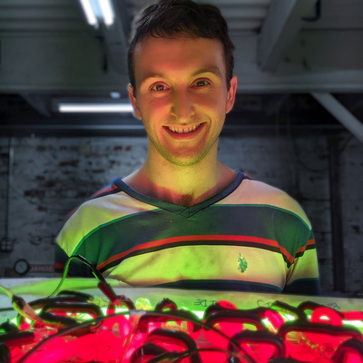
Another piece I put at the Chrysler Glass studio is this 2023 Xenon 9 Shade Handpulled Rainbow. I also whipped up a WeBlink transformer for it that can tune its arc by PWMing the transformer.
Viewers that connect to the pieces wifi network will be able to control the frequency and duty cycle of the transformer and "tame the arc" inside the doodle. I got to see some people interacting with it and it was fun seeing their reactions.
All the colors in this doodle I pulled with my friend Sean Bradley in 2023. A few of them have lots of silver in them. The xenon puts off a lot of UV which makes those silver colors glow in a really neat way. You cannot buy soft glass tubes in these colors, so I made em.
I made a Peertube video with some examples of its lightning being controlled with the web page. check it out to see its wiggly arc.